Instructions
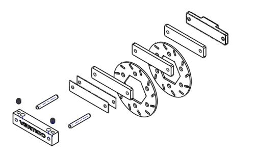
60067Carbon Brakes
1. Remove brake assembly
2. Remove pad material from metal shoes
3. Remove hub pin, add loctite™, replace hub pin.
4. Reinstall discs onto hub (no spacer)
5. Install 2 shims inc/w Baja onto caliper pins
6. Install 3 carbon pads
7. Install brake shoe
8. Fit brake assembly over discs
9. Check adjustment, you may need to add more shims or remove shims. Be sure to install shims on caliper side.
- When installing pins in aluminium caliper Use blue Loctite™ on set screws
VPP1602 Carbon Shock Tower
1. Remove front tower assembly from chassis
2. Assemble 2 piece (long section to rear of assembly)
be sure the counter sunk holes face outwards.
3. Install unit on Chassis
4. Install hinge pins and caster clips.
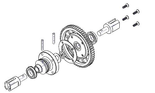
61609 Differential Locker
1. Install gear on locker, due to the gear being cast it is not perfect so tapping the locker into place “may” be necessary, to do this set gear on edge of bench, tap locker ear rotate and continue (Tap lightly)
2. Tighten 4 bolts in criss cross pattern using blue loctite™ to ensure screws will not loosen.
3. Slip “O” ring (included) over locker all the way on.
4. Place bearing onto locker.
5. Grease then slide drive cup into locker.
6. Grease then insert pin, Roll “O” ring into the groove to retain pin.
7. Reinstall gear and grease.
- THIS MODIFICATION MAY CAUSE STRESS ON DRIVE TRAIN
61721 Front Axle Extenders
1. Remove wheel and upper A arm bolt releasing steering knuckle, remove stock hex shaft.
2. Clean bearings, install inner bearing on shaft, install E Clip
3. Slide shaft through knuckle from the rear then reinstall upper A arm bolt completing assembly.
4. Install outer bearing then included extended hub.(Can also use stock rear hub for stock track)
5. Grease then Install pin and wheel, the wheel retains pin
61641 Bearing Carriers
1. Heat carrier in boiling water for 1 minute
2. Remove from water (!!Caution hot!!)
3. Dab any water away from bearing seat
4. Press bearings into place (let cool)
61665 Clutch Cover
- Stock Carrier Removal
1. Remove existing carrier.
2. Remove 3 - 5mm flathead bolts retaining the front of the rear upper plate and upper brake plate.
3. Remove 2 - 4mm socket head bolts holding brake assembly to input shaft carrier.
Remove brake assembly.
4. Remove input shaft carrier.
5. Remove plastic rear engine mount.
- Installation
1. Heat carrier in boiling water or oven. (Expands bearing seats for easy bearing installation)
2. Install included ABEC 5 -12x24 bearings.
3. Install Clutch Bell and Pinion gear into carrier.
4. While lifting the front of the rear plate slide New Vertigo Performance Carrier/Cover into place and attach loosely with 3 - 6mm 5. flathead screws.
6. Install brake assembly and input shaft carrier.
7. Install spur gear plate. (snug bolts only)
8. Install right side front engine mount.
9. Tighten all bolts. (don’t over tighten)
10. Reinstall Spur gear and cover.
- Check bolts after a few minutes of running to ensure they are all tight.
- Over tightened steel bolts can make it difficult to remove bolts in the future.
-100608 Losi 5ive-T Rear spool
Install using blue loctite
Installation of 100911 Losi 5ive Gas Tank Posts
Installation of 61680 HPI Baja Clutch Carrier unit
1. Remove brake assembly
2. Remove pad material from metal shoes
3. Remove hub pin, add loctite™, replace hub pin.
4. Reinstall discs onto hub (no spacer)
5. Install 2 shims inc/w Baja onto caliper pins
6. Install 3 carbon pads
7. Install brake shoe
8. Fit brake assembly over discs
9. Check adjustment, you may need to add more shims or remove shims. Be sure to install shims on caliper side.
- When installing pins in aluminium caliper Use blue Loctite™ on set screws
VPP1602 Carbon Shock Tower
1. Remove front tower assembly from chassis
2. Assemble 2 piece (long section to rear of assembly)
be sure the counter sunk holes face outwards.
3. Install unit on Chassis
4. Install hinge pins and caster clips.
61609 Differential Locker
1. Install gear on locker, due to the gear being cast it is not perfect so tapping the locker into place “may” be necessary, to do this set gear on edge of bench, tap locker ear rotate and continue (Tap lightly)
2. Tighten 4 bolts in criss cross pattern using blue loctite™ to ensure screws will not loosen.
3. Slip “O” ring (included) over locker all the way on.
4. Place bearing onto locker.
5. Grease then slide drive cup into locker.
6. Grease then insert pin, Roll “O” ring into the groove to retain pin.
7. Reinstall gear and grease.
- THIS MODIFICATION MAY CAUSE STRESS ON DRIVE TRAIN
61721 Front Axle Extenders
1. Remove wheel and upper A arm bolt releasing steering knuckle, remove stock hex shaft.
2. Clean bearings, install inner bearing on shaft, install E Clip
3. Slide shaft through knuckle from the rear then reinstall upper A arm bolt completing assembly.
4. Install outer bearing then included extended hub.(Can also use stock rear hub for stock track)
5. Grease then Install pin and wheel, the wheel retains pin
61641 Bearing Carriers
1. Heat carrier in boiling water for 1 minute
2. Remove from water (!!Caution hot!!)
3. Dab any water away from bearing seat
4. Press bearings into place (let cool)
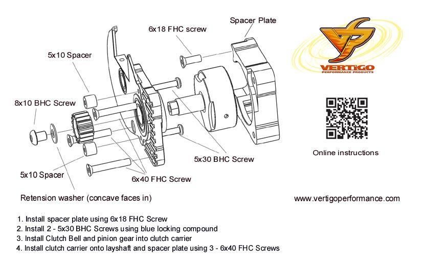
61665 Clutch Cover
- Stock Carrier Removal
1. Remove existing carrier.
2. Remove 3 - 5mm flathead bolts retaining the front of the rear upper plate and upper brake plate.
3. Remove 2 - 4mm socket head bolts holding brake assembly to input shaft carrier.
Remove brake assembly.
4. Remove input shaft carrier.
5. Remove plastic rear engine mount.
- Installation
1. Heat carrier in boiling water or oven. (Expands bearing seats for easy bearing installation)
2. Install included ABEC 5 -12x24 bearings.
3. Install Clutch Bell and Pinion gear into carrier.
4. While lifting the front of the rear plate slide New Vertigo Performance Carrier/Cover into place and attach loosely with 3 - 6mm 5. flathead screws.
6. Install brake assembly and input shaft carrier.
7. Install spur gear plate. (snug bolts only)
8. Install right side front engine mount.
9. Tighten all bolts. (don’t over tighten)
10. Reinstall Spur gear and cover.
- Check bolts after a few minutes of running to ensure they are all tight.
- Over tightened steel bolts can make it difficult to remove bolts in the future.
-100608 Losi 5ive-T Rear spool
Install using blue loctite
Installation of 100911 Losi 5ive Gas Tank Posts
Installation of 61680 HPI Baja Clutch Carrier unit
Specials - [more]
")

Bestsellers
- 100608 Differential Spool (Losi...
- Vertigo Decals
- 120608 Differential Spool (Losi...
- 61902 4x24 mm hardened pins (4)
- 100910 8mm HDV Bolts (4) and...
- 61652-17 Hex Drive Vented clutch...
- 101119 Steel pinion gear (Hex...
- 100652B Hex Drive Clutch Bell w/o...
- 61609 Differential Spool (HPI...
- Wheel adapter (+9mm Hubs)